


Danfoss 003N0107 AVTA 15 Thermostatic Water Valve for Automatic Cooling Control
Danfoss 003N0107 is an AVTA 15 thermostatically operated water valve with G 1/2 internal connections. It uses a brass valve body, an adsorption charge, and an opening action that increases as the sensor temperature rises. The self-acting design regulates cooling-water flow without an external power supply or electronic controller, making it useful for equipment that needs dependable temperature-responsive cooling.
Typical applications include compressors, vacuum pumps, hydraulic systems, engines, heat exchangers, and other machines where cooling water should increase automatically as equipment temperature rises. The sensor is placed at the temperature point being controlled, while the valve modulates water flow according to the thermal charge and setpoint.
Published configuration
Danfoss identifies code 003N0107 as AVTA 15 with G 1/2 connections, a 10 to 80 °C regulating range, and a 2.3 m capillary tube. The published Kv value is 1.9 m³/h. Product data lists a maximum working pressure of 16 bar and a maximum differential pressure of 10 bar. The adsorption charge allows flexible sensor orientation, subject to the installation instructions.
The valve should be sized from the required cooling-water flow and available pressure difference. Selecting a valve only by pipe size can result in poor control. An oversized valve may operate close to its seat and become sensitive, while an undersized valve may not provide enough flow at peak heat load.
| Product data | Published value |
|---|---|
| Code number | 003N0107 |
| Valve type | AVTA 15 thermostatically operated water valve |
| Connections | G 1/2 internal, ISO 228-1 |
| Regulating range | 10 to 80 °C |
| Kv value | 1.9 m³/h |
| Capillary length | 2300 mm |
| Pressure limits | 16 bar maximum working pressure and 10 bar maximum differential pressure |
Sizing the cooling-water circuit
Estimate the heat that must be removed, acceptable temperature rise through the cooling circuit, available supply pressure, outlet pressure, and expected fouling. Use these values to determine water flow and pressure drop. Confirm that the selected valve can deliver the required flow near the middle of its useful operating range. Water quality and strainer requirements should also be considered.
The sensor location should respond to the equipment temperature rather than the cooling-water inlet. Good thermal contact and representative placement are essential. Avoid routing the capillary where it can be crushed, sharply bent, vibrated, or exposed to damaging heat. Leave enough slack for service without allowing the tube to rub against moving equipment.
Installation guidance
Follow the flow-direction arrow and use piping support so the valve body does not carry external loads. Install isolation and straining arrangements that permit service while maintaining plant safety. Protect the sensing bulb with the correct pocket or gland when required by the application. Confirm that the sensor can be removed without damaging the capillary.
Set the temperature gradually and allow the system to reach equilibrium. Verify that water flow increases as the sensed temperature rises. Check for leakage, hunting, insufficient cooling, and excessive water use. If response is slow, inspect sensor contact, capillary condition, valve sizing, water pressure, and fouling before changing the setting.
Maintenance and ordering
Periodically inspect the valve, sensor, capillary, connections, and water circuit. Deposits at the seat or in upstream strainers can restrict flow. Mechanical damage to the capillary requires replacement of the thermostatic assembly. Record the final setting and operating temperature after commissioning.
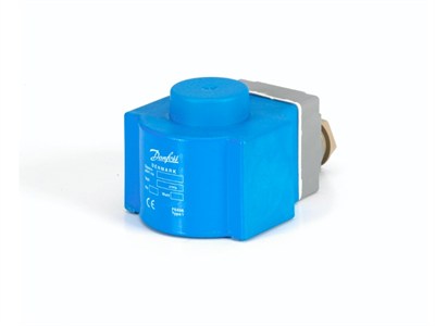
The reused photograph is a general Danfoss component image and does not show the AVTA 15 valve. Buyers should verify code 003N0107, G 1/2 connections, adsorption charge, temperature range, capillary length, and packaging label before acceptance.
