


Eaton Crouse-Hinds MTL662-NA Panel-Mount 4-20 mA Loop-Powered Indicator for Zone 2 Process Monitoring
Choosing the MTL662-NA for Clear Local Indication in a 4–20 mA Process Loop
A control system can show every transmitter value in the control room, yet many plants still need a readable indication beside the process or on the front of a local panel. The Eaton Crouse-Hinds series MTL662-NA addresses that requirement by displaying the current flowing in a 4–20 mA loop. It is a panel-mounted, loop-powered indicator, so it can be added without a separate instrument power supply when the available loop voltage is sufficient.
The model belongs to the MTL660 indicator family, but its full suffix matters. MTL662 identifies the aluminium panel-mount case, while “-NA” identifies the version intended for appropriate Zone 2 use without an intrinsic-safety barrier or galvanic isolator solely for the indicator. MTL662B and MTL662B-NA are backlit variants; they are not the same configuration as the non-backlit MTL662-NA requested here.
Why the low loop voltage drop matters
Every series device consumes part of the voltage available in a current loop. Eaton specifies less than 1 V for the MTL660 display under operating conditions. That is a practical advantage when the loop already includes long field cables, surge protection, an input card, or intrinsic-safety apparatus. It does not remove the need for a voltage-budget calculation, but it makes the indicator easier to accommodate than a device with a larger burden.
Calculate the loop at 20 mA and at the lowest expected supply voltage. Include the transmitter’s minimum operating voltage, cable resistance, the control-system input load, protection devices, and the indicator. A display may work during a bench test yet become unstable after a long cable run or another series load is added. Leaving engineering margin is better than designing exactly to the calculated limit.
MTL662-NA at a glance
Format: aluminium panel-mounted process indicator, approximately 425 g.
Signal: 4–20 mA loop input with published over-range withstand up to 200 mA.
Display: 5½-digit process value plus a separate units and current line.
Environment: published operating range of −25 to +70 °C and storage range of −40 to +80 °C.
Configuration: front-panel selection of range, units, limits, decimal point, and displayed digits.
Variant check: non-backlit “-NA” version; confirm approval marking for the intended Zone 2 installation.
Turning loop current into a useful operator value
The display must be scaled to the transmitter, not merely connected to the loop. If a level transmitter represents 0 to 8 metres, the indicator should show 0.00 at 4 mA and 8.00 at 20 mA, with the correct unit. Pressure, flow, temperature, and analytical measurements need the same agreement between the transmitter range, local indication, and PLC or DCS scaling. Incorrect units or decimal placement can create a believable but wrong reading.
Configuration is performed from the front controls and can be password protected. During commissioning, inject several current values across the range instead of checking only 4 and 20 mA. Mid-scale tests reveal linearity or scaling mistakes that endpoint tests can miss. Compare the local display with a calibrated loop source and the control-system value, then record the final settings in the instrument data sheet.
Panel installation deserves early planning
Confirm the manufacturer’s case drawing before cutting the enclosure. Panel thickness, fixing method, viewing angle, front access, and the overall enclosure rating all affect the installation. Place the indicator where operators can read it without entering an unsafe position. Avoid direct heat, severe vibration, condensation, and chemical exposure beyond the approved limits.
Because the device is connected in series, a loose terminal can interrupt the measurement loop. Use the specified conductor size and terminal torque, support the wiring, and keep instrument cables separated from motor and variable-frequency-drive conductors. Follow the plant standard for shielding and grounding. The “-NA” designation does not replace the site’s hazardous-area assessment or the need to follow the applicable certificate and wiring rules.
How to diagnose a reading disagreement
If the local value and control-room value disagree, first measure the actual current at the same point in the loop. A stable percentage difference usually indicates different scaling, engineering units, or reference ranges. A fluctuating value may indicate electrical noise, an intermittent connection, insufficient loop voltage, or a process-sensor problem. Confirm loop current before adjusting either display; otherwise a wiring fault can be hidden by an incorrect calibration change.
For maintenance, keep the configured lower and upper values, unit text, password procedure, loop drawing, and certificate reference with the instrument record. When replacing a display, verify the complete model rather than accepting another MTL662 family unit by appearance. Backlight, approval, and enclosure suffixes can change supply and installation requirements.
Photograph and purchasing note
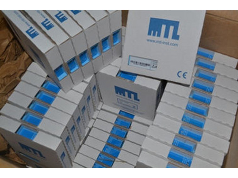
The supplied photograph shows boxed MTL inventory but does not provide a clearly readable MTL662-NA nameplate. It is used as a stock reference, not as proof of the exact indicator configuration. Receiving inspection should confirm the MTL662-NA marking, non-backlit version, aluminium panel case, approval label, accessories, and documentation before the unit is installed or released to the project.
