


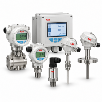
TSP311.A1.K1.N2.Z9(L: 290 MM.).S1.D6.P2.S1.L4.H5.T1.AZ: TSP311 temperature sensor selection: insertion length, thermowell and approval checks
The ABB SensyTemp TSP311.A1.K1.N2.Z9 configuration is listed as a heavy-duty temperature sensor with a stated 290 mm length. TSP311 variants can be supplied without a thermowell for installation in a separate protection assembly. Sensor element, connection head, process interface, extension and approval details are code-dependent, so confirm the full specification against the nameplate and installation drawing.
Key technical data
| Technical item | Verified value / selection note |
|---|---|
| Representative designation | TSP311.A1.K1.N2.Z9 (L: 290 mm) |
| Sensor family | SensyTemp TSP311 for heavy-duty process applications |
| Assembly | Temperature sensor without thermowell in the selected family variant |
| Insertion length | 290 mm stated in the representative description; verify drawing and nameplate |
| Sensor options | RTD or thermocouple selection depends on the ordered element |
| Output arrangement | Direct sensor or transmitter-integrated arrangements exist in the family |
| Approvals and materials | Suffix-specific; verify process temperature and hazardous-area requirements |
The table summarizes family or catalog values for identification and initial selection. Confirm the nameplate, environmental limits, standards, revision and options for the exact device before procurement or engineering approval.
Application and system selection
A sensor assembly must be matched to the thermowell, process temperature, pressure, vibration and response-time requirements. Check insertion depth and tip location against the process profile, and determine whether a replaceable insert or integrated transmitter is needed. The measurement chain includes the sensor, extension, terminal arrangement and host input configuration.
Configuration and compatibility
Review the exact suffix for RTD or thermocouple type, wire count, head material, process connection, extension length and certifications. The 290 mm description should not be assumed to equal the effective insertion length. Confirm whether the assembly includes a thermowell; this representative family variant is described without one.
Related models and order-code references
The following designations are related catalog references, not automatic substitutes. Check each complete code, rating, connection, revision and application requirement before selecting a variant.
- TSP311-A1.K1.M3.Z9.T1.D8.K1.T2.S4.H4/AZ.C6.P1.V1.U1.L2.M5.T1 AZ: 0~1100°C Z9=3000mm
- TSP311-A1.K1.M3.Z9.T1.D8.K1.T2.S4.H4/AZ.C6.P1.V1.U1.M5.T1 AZ: 0~1100°C
- TSP311-A1.Y0.M3.U4.T1.D8.T2.B2.S4.H4/AZ.C6.P1.V1.U1.M5.T1 AZ: 0~1100°C
- TSP311-A1.Y0.M3.U4.T1.D8.T2.D1.S4.H4/AZ.C6.P1.V1.U1.M5.T1 AZ: 0~1100°C
- TSP311.A1.K1.N4.Z9.S1.D6.P5.S1.L1.Y1 .CE..GHE.P3.V6.U1..PV.M5...T1
- TSP311.A1.S1.K1.N4.Z9.S1.D6.P2.S1.L4.H5.AZ.CS.P3.V6.K6.J9.J2.JZ.H8.U1.L2.T1 Z9:365MM
- TSP311.A5.K1.A2.U6.S1.D6.P5.B2.S4.H6-A0.L1
- TSP311.A5.K1.N3.Z9.S1.D6.P2.S1.L1.H4.AZ.C4.C6.CS (Z9:440MM AZ:-50°C TO +400°C)
- TSP311.A5.K1.N3.Z9.S1.D6.P2.S1.L1.H5-AZ.C4.C6.CS.U5.M5.C07.T1.T2 Z9:U=230MM
- TSP311.A5.K1.N3.Z9.S1.D6.P2.S1.L4.H5-AZ.C4.C6.CS.U5.L1.M5.C07.T1.T2 Z9:U=200 MM
- TSP311.A5.K1.N3.Z9.S1.D6.P2.S1.L4.H5/AZ.C4.C6.CS.U5.L1.M5.C07.T1.T2 (Z9:440MM AZ:-50°C TO +400°C)
- TSP311.A5K1N3Z9S1D6P2S1L1H5-AZC4C6CSU5M5C07T1T2 (440MM )
- TSP311.A5K1N3Z9S1D6P2S1L4H5-AZC4C6CSU5L1M5C07T1T2(450MM)
- TSP311.H5.W2.N3.W2.D1.D6.P2.D2.S4.H7-A0.CD.P1.V2.L1SP
Installation and commissioning
Install using the process connection and torque specified for the assembly, preserving clearance from vessel walls and avoiding mechanical strain on the sensor. Check continuity, insulation resistance and polarity as applicable, then compare readings with a calibrated reference. Document the sensor type, insertion length and transmitter/input scaling.
Replacement and procurement information
For a quotation or replacement review, provide the complete designation TSP311.A1.K1.N2.Z9(L: 290 MM.).S1.D6.P2.S1.L4.H5.T1.AZ, the order code where applicable, serial or hardware revision, quantity, operating environment, connected equipment and required delivery date. Include a legible nameplate image and relevant wiring, loop or switchgear drawing so the exact interface and configuration can be checked.
Ask the supplier to confirm accessories, revision compatibility and any approved successor in writing. Do not select solely from a family name or product photograph. Follow the current ABB installation and safety instructions for the exact unit.
