


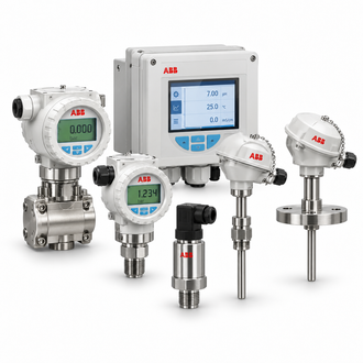
LMT200.E1.S6.R1.B1.D2.L2.H1-S1 (1000MM): LMT200 level transmitter: magnetic-gauge fit, float travel and output verification
The ABB LMT200.E1.S6.R1.B1.D2.L2.H1-S1 (1000MM) designation identifies a magnetostrictive level-transmitter configuration intended for external mounting on a compatible magnetic level gauge. ABB describes LMT200 for total and interface level measurement, with a family performance reference of 0.01% of full scale or ±1.27 mm, whichever is greater. Confirm the actual sensor length and gauge geometry before ordering.
Key technical data
| Technical item | Verified value / selection note |
|---|---|
| Representative designation | LMT200.E1.S6.R1.B1.D2.L2.H1-S1 (1000MM) |
| Measurement principle | External-mount magnetostrictive sensing with magnetic float |
| Nominal probe length | 1000 mm as stated in the representative designation; verify as-built dimension |
| Output | 4–20 mA with HART family option; FOUNDATION Fieldbus also available by version |
| Typical performance | 0.01% full scale or ±1.27 mm, whichever is greater, family reference |
| Applications | Total level and interface level on compatible magnetic level gauges |
| Mounting | Non-intrusive external mount; gauge and float compatibility is essential |
The table summarizes family or catalog values for identification and initial selection. Confirm the nameplate, environmental limits, standards, revision and options for the exact device before procurement or engineering approval.
Application and system selection
LMT200 measures float position without inserting a conventional probe into the process. Selection therefore depends on the magnetic gauge chamber, float type, measuring span, mounting orientation and process temperature. For interface service, verify that the float responds to the liquid-density boundary expected at the site.
Configuration and compatibility
Compare the exact length and housing/output suffix with the installed gauge. Verify mounting brackets, float travel, output protocol, hazardous-area approval and the distance between transmitter and gauge reference points. A length printed in a catalog description should be checked against the actual installation drawing and nameplate.
Related models and order-code references
The following designations are related catalog references, not automatic substitutes. Check each complete code, rating, connection, revision and application requirement before selecting a variant.
- LMT200.E1.S6.R1.B1.D2.L2.H1-S1 (2000MM)
- LMT200.E1.S6.R1.B1.D3.L2.H1-CS.M5.R5 (600MM)
- LMT200.E1.S6.R1.B1.D3.L2.H1.TS.S1
- LMT200.E2.S6.R1.B1.D1.L2.H1 - 1295MM
- LMT200.E2.S6.R1.B1.D1.L2.H1 - 381MM
- LMT200.E2.S6.R1.B1.D2.L2.H1-CS..GD1.GD3.M5.R5//23.5IN
- LMT200.E2.S6.R1.B1.D3.L2.H1-TS//GS1.M5.R5.800.00MM
- LMT200.E2.S6.R1.T1.D2.L2.H1
- LMT200.M1.S6.R1.B1.D2.L2.H1-TS // GD2.M5.R3 ML = 39 IN
- LMT200.M1.S6.R1.B1.D2.L2.H1-TS.AV//GD.1.M5 ML=1200MM
- LMT200.M1.S6.R1.B1.D3.L2.F1
- LMT200.M1.S6.R1.B1.D3.L2.H1.TS.AV /GD2.M5. ML ( 1650MM)
- LMT200.M1.S6.R1.B1.D3.L2.H1.TS.AV /GD2.M5.ML (600MM )
- LMT200.M1.S6.R1.T1.D1.L2.H1–CS.TS.S1.AV/GD2.M5 ML = 36 INCHES
- LMT200.M1.S6.R1.T1.D3.L2.H1-M5.R3
- LMT200.N2.S6.R1.B1.D4.L2.H1 PROBE LENGTH: 16 INCH
- LMT200.Y0.S6.R1.B1.D1.L2.H1-M5.R3 ML=700MM
Installation and commissioning
Mount the transmitter parallel to the gauge and follow the manufacturer’s alignment and clearance instructions. Confirm the float moves freely through the measurement range, then set zero and span to match the vessel’s datum. Verify analog/HART output at known level points and record the configured engineering range and alarm behavior.
Replacement and procurement information
For a quotation or replacement review, provide the complete designation LMT200.E1.S6.R1.B1.D2.L2.H1-S1 (1000MM), the order code where applicable, serial or hardware revision, quantity, operating environment, connected equipment and required delivery date. Include a legible nameplate image and relevant wiring, loop or switchgear drawing so the exact interface and configuration can be checked.
Ask the supplier to confirm accessories, revision compatibility and any approved successor in writing. Do not select solely from a family name or product photograph. Follow the current ABB installation and safety instructions for the exact unit.
