


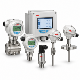
AWT420.A.1.A1.C2.P1.Y0.E5-A2.U1.M5: AWT420 analyzer transmitter: sensor pairing, measurement channels and communications
The ABB AWT420.A.1.A1.C2.P1.Y0.E5-A2.U1.M5 is an AWT420 universal water-analysis transmitter configuration. The family accepts up to two analog or digital sensors and supports pH/ORP, conductivity, optical dissolved oxygen and turbidity/suspended-solids measurements. Supply, enclosure, sensor channels and communications depend on the ordered options and must be verified from the nameplate.
Key technical data
| Technical item | Verified value / selection note |
|---|---|
| Representative designation | AWT420.A.1.A1.C2.P1.Y0.E5-A2.U1.M5 |
| Transmitter type | Universal four-wire AWT420 family |
| Sensor inputs | Up to two analog or digital sensors, depending on fitted EZLink channels |
| Supported measurements | pH/ORP, conductivity, optical dissolved oxygen and turbidity/suspended solids |
| Supply | 100–240 V AC or 24 V DC family options |
| Enclosure | IP66 / NEMA 4X family reference |
| Communications | Optional Ethernet, PROFIBUS DP, Modbus RTU or HART; verify fitted option |
The table summarizes family or catalog values for identification and initial selection. Confirm the nameplate, environmental limits, standards, revision and options for the exact device before procurement or engineering approval.
Application and system selection
Choose the transmitter after defining the water-quality parameters and the actual sensor technology. Confirm whether one or two channels are needed, sensor cable lengths, cleaning requirements, process mounting and calibration intervals. Municipal water, wastewater, industrial utilities and power applications can require different sensor materials and maintenance routines.
Configuration and compatibility
Decode the complete order string only against ABB’s version-specific ordering guide. Confirm the sensor input boards, digital EZLink channel, analog channel, power supply, enclosure material, display and communication module. Check the host protocol and register map before tying the analyzer into a PLC or DCS.
Related models and order-code references
The following designations are related catalog references, not automatic substitutes. Check each complete code, rating, connection, revision and application requirement before selecting a variant.
- AWT420.A.1.A1.C4.C4.Y0.E5-A1.U3.M5
- AWT420.A.1.A1.P1.Y0.Н1.E5.U1.M5
- AWT420.B.1.A1.C2. Y0.Y0.E5-.U3.M5
- AWT420.B.1.A1.C2.C2.Y0.E5-A1
- AWT420/B.1.A1.C2.P1.Y0.E5.M5
- AWT420/B.1.A1.C2.Y0.Y0.E5.M5
- AWT420/B1A1C2C2Y0E5A1U3M5
- AWT420/B1A1D1D1Y0E5A1U3M5
Installation and commissioning
Mount the enclosure where the display and cable entries remain accessible, protect sensor leads from interference and follow the sensor-specific immersion or insertion requirements. Configure each measurement channel and temperature compensation, then calibrate with appropriate standards. Verify alarm relays, communications and diagnostics before relying on the readings for process decisions.
Replacement and procurement information
For a quotation or replacement review, provide the complete designation AWT420.A.1.A1.C2.P1.Y0.E5-A2.U1.M5, the order code where applicable, serial or hardware revision, quantity, operating environment, connected equipment and required delivery date. Include a legible nameplate image and relevant wiring, loop or switchgear drawing so the exact interface and configuration can be checked.
Ask the supplier to confirm accessories, revision compatibility and any approved successor in writing. Do not select solely from a family name or product photograph. Follow the current ABB installation and safety instructions for the exact unit.
