


ABB TTF300.E4.C1.H.BS./OPT Field-Mount Temperature Transmitter for Dual-Sensor Process Loops
Field-Mounted Temperature Conversion with the ABB TTF300
ABB TTF300.E4.C1.H.BS./OPT is a configured member of the TTF300 field-mount temperature transmitter family. The platform is designed to accept common industrial temperature-sensor signals and convert them into a standardized process output close to the measurement point. Its field housing makes it suitable for plants that need local indication, accessible commissioning, and protection from normal industrial environmental conditions.
The TTF300 family supports universal sensor inputs such as resistance temperature detectors, thermocouples, resistance, and millivolt signals. ABB offers communication variants including 4–20 mA with HART, PROFIBUS PA, and FOUNDATION Fieldbus. The exact protocol, electrical protection, display, approvals, and enclosure material depend on the full order code. Buyers should not infer every option from a short family description.
Redundancy and diagnostics for important loops
One reason engineers specify a two-channel transmitter is the ability to use two sensor inputs for backup, comparison, or selected measurement strategies. In a compatible configuration, sensor redundancy can keep a process value available after a sensor fault. Drift and sensor-break monitoring can also help maintenance teams distinguish a failed element from a real process change. These functions must be configured and tested; they are not automatic substitutes for a documented reliability or safety design.
For a retrofit, confirm the sensor type, wire configuration, measuring range, cold-junction requirements, linearization, burnout direction, damping, output scaling, alarm current, and tag data. A transmitter can power up correctly yet report a wrong value if the sensor wiring or engineering range is entered incorrectly. Loop verification should therefore include at least one known input point and a check at the receiving PLC or DCS.
| Buyer check | Details to confirm |
|---|---|
| Model | TTF300.E4.C1.H.BS./OPT |
| Input | Sensor type, one or two channels, 2/3/4-wire connection and measurement range |
| Output | 4–20 mA HART, PROFIBUS PA or FOUNDATION Fieldbus as ordered |
| Housing | Material, cable entries, display, environmental and hazardous-area approvals |
| Documentation | Calibration, certificates, language, tag and project records |
Practical installation review
Choose a mounting location that limits excessive vibration, radiant heat, condensation, and direct mechanical damage while keeping the display and terminals accessible. Cable glands and unused entries must preserve the enclosure rating. Separate low-level sensor wiring from power cables and variable-frequency-drive outputs. Shielding and grounding should follow the sensor, plant, and manufacturer instructions rather than a single generic rule.
When two sensors are used, record which input is primary and how the output behaves during open-circuit, short-circuit, mismatch, or drift conditions. Confirm that the control system interprets status and alarm currents correctly. For digital communication, verify device revision, host files, addressing, update behavior, and asset-management integration before commissioning the loop.
Calibration and lifecycle considerations
Transmitter accuracy is only one part of the complete temperature-loop uncertainty. The sensor class, thermowell conduction, immersion length, wiring resistance, cold-junction compensation, transmitter configuration, ambient temperature, and control-system input all contribute. Establish the required loop accuracy and response time first, then decide whether a one-point trim, two-point trim, matched sensor-transmitter calibration, or system calibration is appropriate. Keep the factory certificate and any site calibration results with the instrument tag.
Maintenance teams benefit from a saved parameter record that includes input type, range, units, damping, alarm direction, channel strategy, output mapping, and diagnostics. After replacing a sensor or transmitter, verify polarity, lead arrangement, range, and control-system scaling before returning the loop to service. For safety-related duties, use the approved safety manual for the installed hardware and firmware and document proof-test intervals and results. Hazardous-area installations also require compatible glands, barriers, wiring methods, and certificates for the complete loop.
What purchasing teams should request
A useful inquiry includes the complete model string, quantity, sensor element and wiring, calibrated range and units, required output protocol, power supply, housing material, display preference, cable-entry thread, ambient conditions, area classification, required approvals, and certificate package. State whether the unit is a direct replacement and provide the old nameplate and terminal photographs.
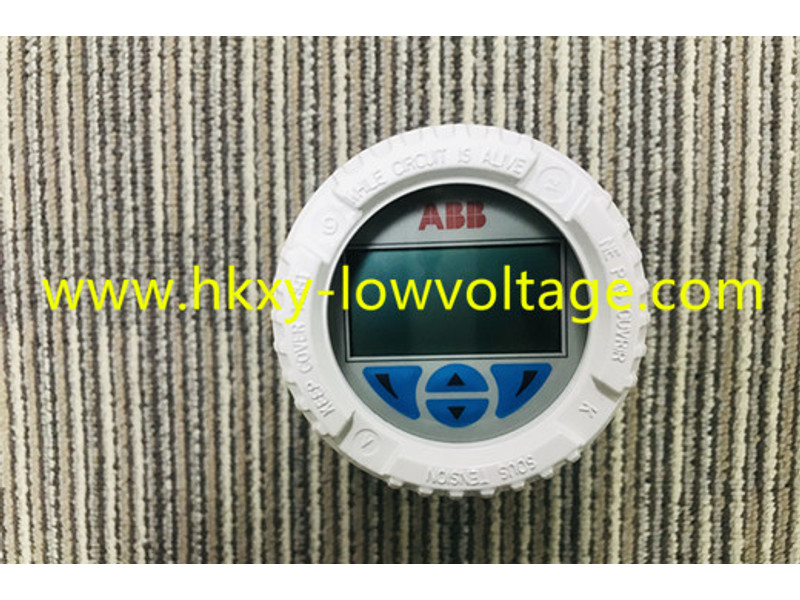
ABB lists accuracy, stability, diagnostics, enclosure protection, and functional-safety options at family level, but the ordered suffix determines what is actually supplied. Verify the current product datasheet and ABB configuration documents for this exact code before purchase. The image is a reference photograph of a TTF300-style field housing; nameplate and option details should be checked on delivery.
