

Applying Yokogawa UT55A-010-10-00 to Temperature and Process Control
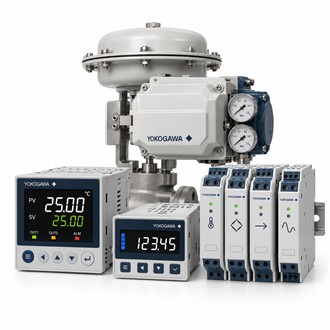
Yokogawa UT55A-010-10-00 is a digital indicating controller for measured-variable control in industrial processes. The UT55A family is commonly selected for temperature loops, but the controller’s actual fit depends on the sensor input, output hardware, control strategy and panel arrangement specified for the order. Confirming these details at the outset makes UT55A-010-10-00 easier to evaluate for a new panel or a like-for-like service replacement.
At a glance
| Item | Details |
|---|---|
| Representative model | UT55A-010-10-00 |
| Product family | UT55A digital indicating controller |
| Typical role | Process-variable indication and control |
| Input choices | Thermocouple, RTD, voltage or current, subject to the order configuration |
| Control options | Selectable control functions and output hardware |
| Order check | Sensor, range, output, supply, communication and panel fit |
Start with the measured input
The UT55A supports universal input choices that can include thermocouples, resistance temperature detectors, voltage and current, depending on configuration. Confirm the sensor type and range, wiring method, engineering units and any input scaling before assigning UT55A-010-10-00 to a loop. A sensor that can be physically connected is not necessarily a valid selection unless its input type and configured range agree with the process design. Record the sensor and transmitter details alongside UT55A-010-10-00 in the control-loop documentation.
Control behavior and output checks
UTAdvanced controllers provide selectable control functions, including PID-related functions, while available control outputs and communications depend on the ordered hardware. For UT55A-010-10-00, compare the required heating or cooling action, output signal, alarm behavior and manual/automatic operating procedure with the loop narrative. Check whether the final element expects a relay, voltage pulse, current signal or another supported output. These checks help prevent a model-family match from being mistaken for a complete functional match.
Panel installation and commissioning
Before commissioning UT55A-010-10-00, verify panel cutout, supply, terminal assignment, grounding and separation of sensor wiring from switching or motor conductors. Use the project drawings and the applicable instrument manual for terminal-level work. During startup, confirm that the displayed process value follows a known reference, that alarms operate at the intended thresholds and that output action is correct across the operating range. Document the parameter set so future maintenance can distinguish configuration changes from hardware faults.
Replacement decision
When replacing an installed controller with UT55A-010-10-00, compare the complete code on the nameplate rather than selecting by the UT55A family name alone. Check control-loop logic, input/output assignment, communication requirements, mounting and configured alarms. If any of these differ, plan an engineering review and controlled commissioning rather than assuming a direct swap. For quotation, provide the full model, panel or nameplate photographs, quantity and destination so the requested configuration can be checked before dispatch.
Other UT55A model codes
- UT55A-030-11-00
- UT55A-100-10-00
- UT55A-NNN-11-UN
- UT55A-NNN-11-U1
- UT55A-NNN-11-CC3
Information to include with an enquiry
Send the exact suffix of UT55A-010-10-00, a clear nameplate photograph and the loop’s sensor/output requirements when requesting a quotation. This information allows the selected controller to be compared with the actual panel design rather than only with a series description.
Keep the exact UT55A order code UT55A-010-10-00 in the equipment and purchasing record.
