


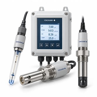
Configuring FLXA202-D-B-D-AB-P1-NN-A-N-LA-N-NN/U for Liquid Analysis
Yokogawa FLXA202-D-B-D-AB-P1-NN-A-N-LA-N-NN/U belongs to the FLXA202 two-wire liquid analyzer family. The platform supports configurable measurements and can accept one or two sensors, with the measurement modules in a dual-sensor arrangement required to be for the same parameter. That makes the sensor plan—not just the transmitter label—the starting point for selecting FLXA202-D-B-D-AB-P1-NN-A-N-LA-N-NN/U and for assessing the related model codes listed below.
At a glance
| Item | Details |
|---|---|
| Representative model | FLXA202-D-B-D-AB-P1-NN-A-N-LA-N-NN/U |
| Analyzer | FLXA202 modular 2-wire liquid analyzer/transmitter |
| Available measurement types | pH/ORP, contacting conductivity, inductive conductivity or dissolved oxygen |
| Sensor count | One or two; dual-sensor modules must use the same measurement parameter |
| Loop interface | 4–20 mA with HART on supported configurations |
| Selection priorities | Sensor type, module, loop, cable, approvals and enclosure |
Choose the measurement parameter
FLXA202 configurations cover pH/ORP, contacting conductivity, inductive conductivity and dissolved oxygen. These are different measurement systems with different sensor and wiring requirements. Specify the process parameter, expected range, temperature compensation needs and sensor technology before ordering FLXA202-D-B-D-AB-P1-NN-A-N-LA-N-NN/U. Where two sensors are intended, confirm that the chosen modules support the same parameter and that the intended use—independent readings, calculated values or redundancy—is supported by the project configuration.
Use diagnostics as part of maintenance planning
The analyzer’s sensor health and diagnostic functions can help operators identify changes such as fouling, deterioration or wiring issues, depending on the measurement type. Decide how the display, alarm values and maintenance workflow should present these conditions. For FLXA202-D-B-D-AB-P1-NN-A-N-LA-N-NN/U, agree on calibration materials, cleaning intervals, sensor replacement criteria and who is responsible for recording the results. These practical details can reduce uncertainty when a process reading drifts or maintenance is scheduled.
Review the loop and environment
As a two-wire device, the selected analyzer configuration must fit the loop supply, 4–20 mA signal path, HART requirements and any area classification. Confirm enclosure material, mounting, cable entries and barrier requirements against the site design. Before commissioning FLXA202-D-B-D-AB-P1-NN-A-N-LA-N-NN/U, verify the sensor cable and terminal mapping, configure engineering units and temperature compensation, and test the analog output across the expected operating range.
Compare full codes carefully
The model string records a particular analyzer build, while nearby FLXA202 codes may select different sensor inputs or options. Do not assume that a suffix change is cosmetic. For FLXA202-D-B-D-AB-P1-NN-A-N-LA-N-NN/U, compare the existing order code with the requested replacement, installed sensor model, communication needs and approval documentation. If the application has changed, reselect the analyzer and sensor as a system rather than copying an old code automatically.
FLXA202 model codes
- FLXA202-D-B-D-AB-P1-NN-A-N-LA-N-NN
- FLXA202-D-B-D-AB-P1-NN-A-N-LA-N-NA/U
- FLXA202-D-B-D-AB-P1-NN-A-N-LA-N-NA
Information to include with an enquiry
For FLXA202-D-B-D-AB-P1-NN-A-N-LA-N-NN/U, provide the analyzer and sensor nameplates, measurement parameter, loop wiring, installation area and desired communication functions. A model-code comparison is most reliable when the sensor and transmitter are reviewed together.
Keep the exact FLXA202 order code FLXA202-D-B-D-AB-P1-NN-A-N-LA-N-NN/U in the equipment and purchasing record.
