


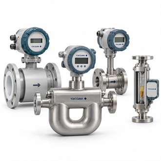
Selecting the Yokogawa AXG200-GA000AA1AH212B-2M611/GRL Flowmeter
The Yokogawa AXG200-GA000AA1AH212B-2M611/GRL is a specific ADMAG TI AXG electromagnetic flowmeter configuration. Magnetic flow measurement is intended for electrically conductive liquids, so process conductivity and a suitable full-pipe installation are fundamental checks. Use the complete code for AXG200-GA000AA1AH212B-2M611/GRL when comparing a proposed spare; AXG200 models may differ in construction, connection, materials and output options.
At a glance
| Item | Details |
|---|---|
| Representative model | AXG200-GA000AA1AH212B-2M611/GRL |
| Technology | Electromagnetic induction for conductive liquid flow |
| Product family | ADMAG TI AXG magnetic flowmeter |
| Selection inputs | Conductivity, flow range, line size, process conditions and materials |
| Installation review | Grounding, full-pipe conditions, orientation and converter location |
| Order-code practice | Verify the complete AXG200 string and options from the nameplate |
Process suitability comes first
Confirm that the liquid is conductive and that the selected meter construction is appropriate for the fluid. Review normal and upset flow, temperature, pressure, solids or coating tendencies, chemical compatibility and cleaning requirements. For AXG200-GA000AA1AH212B-2M611/GRL, the wetted liner and electrode materials must be checked against the real process chemistry; a general statement that the meter is electromagnetic does not establish material compatibility.
Size and installation
Match nominal diameter to the line and operating range rather than treating pipe size as the only sizing input. Review expected velocity, reducer layout, flow direction, grounding and whether the tube can remain full under all operating conditions. The converter may be integral or remote depending on the selected construction. Verify the installed arrangement for AXG200-GA000AA1AH212B-2M611/GRL against the piping and instrumentation drawings and available cable route.
Signals and plant integration
Identify the receiving control system and required output, status or communication interface. Check power supply, output assignment, hazardous-area approvals and local display needs as part of the ordering review. When assessing AXG200-GA000AA1AH212B-2M611/GRL as a replacement, preserve the configured range and unit, damping and any flow-direction or empty-pipe settings used by the process. These parameters influence how the instrument behaves in the loop even when the physical sensor is correct.
Commissioning notes
After installation, inspect grounding and bonding, confirm the converter/sensor pairing and verify the measured value against a known operating condition or independent reference. Document the zero check and final configuration. The longer model string for AXG200-GA000AA1AH212B-2M611/GRL should remain in the maintenance record together with sensor serial data and software/configuration notes, so the next replacement decision is based on a traceable instrument record rather than visual similarity.
Other AXG200 model codes
- AXG200-GA000BE3AL214B-2JA12/GRL/CH
- AXG200-GA000BE3AL214B-2JA12/GRL
- AXG200-GG000AE2CE214B-NNNNN
- AXG200-GG000BA1AT222B-NNNNN/GRT/GA
- AXG200-GG000CA1AL224B-NNNNN/SCT/E01/T01/SC/EC/Z
Information to include with an enquiry
When requesting a quote for AXG200-GA000AA1AH212B-2M611/GRL, attach the full nameplate, nominal size, fluid description, flow range, process pressure/temperature, output requirement and converter arrangement. This information lets the requested AXG200 build be checked against the actual operating service.
Keep the exact AXG200 order code AXG200-GA000AA1AH212B-2M611/GRL in the equipment and purchasing record.
