


Verifying SB2427 before order and commissioning
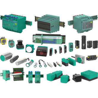
Pepperl+Fuchs SB2427 is a two-channel Zener barrier used to limit energy transfer from safe-area wiring into a hazardous-area circuit. This page keeps the exact SB2427 designation visible for buyers and maintenance personnel. The shared product main image is a category montage, not an exact photograph of SB2427. Confirm the latest manufacturer record and installed label before using any figure to specify a replacement.
Technical data and selection limits
| Technical item | Verified value / selection note |
|---|---|
| Exact model | SB2427 |
| Product role | two-channel Zener barrier |
| Channels | 2 |
| Polarity | Positive DC |
| Working voltage | 24 V at 2 µA |
| Fuse | Replaceable 32 mA fuse |
| Variant check | Confirm the complete designation and current manufacturer documentation before replacement. |
Purpose in the process
The operational role of SB2427 is to limit energy transfer from safe-area wiring into a hazardous-area circuit. Document the expected input condition and the required output or mechanical response. A change in host electronics, wiring, hazardous-area classification or process medium can alter whether SB2427 remains suitable. Similar-looking designations listed below are inventory references only, not declared substitutes.
Installed assembly
For SB2427, start with the real installation rather than the appearance of a similar component. Record the mating device, drawing revision, power supply, connection, mounting position and environmental conditions. The complete SB2427 code is the ordering key. Accessories and certificates may be separate line items, so request confirmation of the entire installed assembly.
Functional acceptance
To accept SB2427, observe a known normal state and a known changed state at the connected host. Record the measured values, output indication and controller response. Where adjustment or configuration exists, preserve its settings before removing the former unit. Check the working-range edge and repeat the test after final mechanical fixing of SB2427.
Mounting and connection
Before installation of SB2427, Check field loop calculation, grounding and the matching terminal base. Inspect the exact terminals, mechanical engagement and clearance against the manufacturer's drawing. If the installation is Ex-rated or safety-related, validate the complete certified circuit and site procedure. Do not copy limits from a visually similar suffix onto SB2427.
Order description
An enquiry for SB2427 should include the exact printed code, quantity, host or mating accessory, approval need and a label photograph. The technical table identifies confirmed values for SB2427; any uncertain variant choice is explicitly a verification item. Request the appropriate document for every alternative suffix and retain the approved selection with the maintenance file.
Other visually related designations
Codes below resemble SB2427 in print but may differ in function, ratings, fit or approvals. Verify each full designation independently.
No additional same-pattern designation is grouped with SB2427 here.
Service close-out
Handover for SB2427 is complete only when the fitted marking, drawing, test result and purchasing record match. Keep the photos and settings so a later team can recognize SB2427 without guessing from the shared image or the related-code index.
