


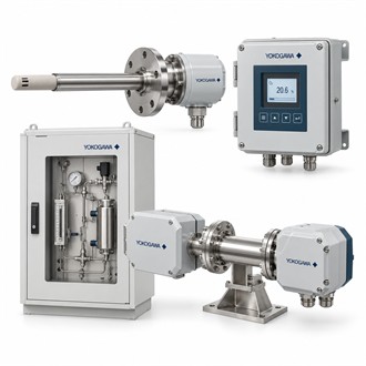
In-Situ Gas Measurement with Yokogawa TDLS8000G1A1U3A1NN+YH8000G1ENM
Yokogawa TDLS8000G1A1U3A1NN+YH8000G1ENM identifies a configured TDLS8000 analyzer/HMI system. TDLS8000 measurements depend on the selected absorbing component, range and optical arrangement. Before specifying TDLS8000G1A1U3A1NN+YH8000G1ENM, define the target gas, expected and upset concentration, process temperature and pressure, dust loading, corrosive species and measurement path. The complete configuration must be reviewed for the actual gas stream.
Specification snapshot
| Selection point | Specification / confirmation |
|---|---|
| Representative model | TDLS8000G1A1U3A1NN+YH8000G1ENM |
| Analyzer | TDLS8000 tunable diode laser spectrometer |
| Measurement approach | In-situ optical measurement; gas component depends on configuration |
| Possible components | O₂, CO, CH₄, CO₂, H₂O, NH₃, H₂S or HCl subject to build |
| HMI | YH8000 local/remote operator interface in this combined model string |
| Application check | Confirm gas, range, path, process conditions, purge and mounting |
In-situ arrangement and process conditions
The TDLS8000 platform is designed for in-situ measurement and can avoid a conventional extracted sample-conditioning train in suitable applications. For TDLS8000G1A1U3A1NN+YH8000G1ENM, assess the process window, path length, alignment, vibration, access, temperature and pressure limits. The analyzer's optical interfaces may require suitable purging or process insulation depending on gas conditions; these are application-specific engineering details, not assumptions to make from the base code.
HMI and operating practice
This model string includes YH8000, an HMI intended for TDLS8000 operation. Confirm mounting location, display access, cable routing, communications and the number of analyzers served in the proposed architecture. For TDLS8000G1A1U3A1NN+YH8000G1ENM, commissioning should verify analyzer alignment and signal quality, configured measurement component and range, zero/span or validation method, alarms and communications to the control system.
System scope and inquiry details
The submitted code combines analyzer and HMI configuration, but project scope may also include process interfaces, insulation flange, calibration/validation accessories and installation materials. For TDLS8000G1A1U3A1NN+YH8000G1ENM, provide a process data sheet, gas composition, measurement range, pipe/duct dimensions, hazardous-area classification, environmental conditions and required output/interface. For model-code verification, retain TDLS8000G1A1U3A1NN+YH8000G1ENM with the process data. This information helps establish what belongs in the analyzer package and what must be engineered separately.
Information for model verification
For TDLS8000G1A1U3A1NN+YH8000G1ENM, include the complete nameplate code, application, interface and operating conditions in an enquiry. Retain TDLS8000G1A1U3A1NN+YH8000G1ENM with the equipment record and verify the exact specification before replacement or project release. Record the exact model code TDLS8000G1A1U3A1NN+YH8000G1ENM in the purchase request.
