


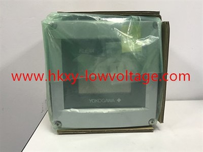
Yokogawa FLXA21 Fieldbus Conductivity Analyzer for Water Quality and Utility Systems
The Yokogawa FLXA21-D-P-D-AB-C1-NN-F-N-LA-N-NN/CD4 is a two-wire contacting-conductivity analyzer configured for FOUNDATION Fieldbus communication. It brings conductivity, resistivity, temperature, device status, and configuration data into a compatible digital control network. The C1 input is intended for an appropriate contacting-conductivity sensor, while the second input position is NN, indicating a single measurement channel in this requested configuration.
Plants often use this arrangement where analytical data must be visible beyond a single analog value. Boiler and condensate systems, demineralization trains, reverse-osmosis skids, cooling-water networks, clean-in-place systems, and chemical dilution services can benefit from centralized diagnostics and configuration. The value of the network depends on correct sensor selection, installation, and lifecycle discipline.
Matching range to sensor cell constant
Conductivity sensors convert the electrical behavior of the liquid into a measurement related to ionic concentration. Their cell constant strongly influences the practical range. Yokogawa lists FLXA21 contacting-conductivity support for cell constants from 0.005 to 50 cm⁻¹ across the family. Low constants are commonly associated with cleaner, lower-conductivity water, while larger constants can suit more conductive solutions. Electrode material and geometry must also tolerate the process.
Define the normal range, startup condition, cleaning chemicals, temperature swing, pressure, and contamination risk. A sensor chosen only for the nominal value may polarize, coat, corrode, or lose sensitivity during an upset. For high-purity measurements, sample-line materials, atmospheric carbon dioxide, flow, and temperature stability can dominate the error budget.
| Selection item | Specified configuration |
|---|---|
| Model code | FLXA21-D-P-D-AB-C1-NN-F-N-LA-N-NN/CD4 |
| Measurement | Contacting conductivity or resistivity with a compatible C1 sensor |
| Communication | FOUNDATION Fieldbus, F output code |
| Housing | Plastic enclosure with anti-glare touch display |
| Approval | AB general-purpose CE/RCM configuration |
| Mechanical option | /CD4 conduit adapter; confirm entry thread and site standard |
Temperature compensation and data interpretation
Conductivity changes with temperature even when chemical concentration remains constant. Configure the correct temperature element and compensation method for the sensor. NaCl compensation can be useful for many aqueous applications, while high-purity water or a specific chemical may require a different relationship. Always distinguish raw conductivity, compensated conductivity, resistivity, concentration, and temperature when mapping values to the control system.
A useful fieldbus design exposes the values and status needed for maintenance without overwhelming operators. Decide which parameter is primary, how bad or uncertain status will be handled, and whether diagnostic alerts are routed to an asset-management system. Trend temperature together with conductivity so a process change can be separated from a compensation or sensor issue.
Segment and installation checks
Confirm the host supports the analyzer revision and that the correct device files are available. Calculate segment voltage and current with the power supply, conditioner, barriers if applicable, trunk, spurs, and all connected devices. Use approved fieldbus cable, place terminators correctly, and apply the project’s shielding and grounding practice. The AB configuration is general purpose, so do not install it in a classified area that requires an intrinsically safe approval.
The /CD4 option should be checked against the conduit system before delivery. Incorrect thread selection can delay commissioning or tempt unsafe adapters. Mount the enclosure where it is visible and serviceable, protect cable entries from water, and route the conductivity sensor cable away from motor leads and variable-frequency-drive outputs.
Commissioning and troubleshooting
Enter the cell constant, temperature element, units, range, compensation, damping, and diagnostic settings from the sensor documentation. Check the reading with a suitable standard or controlled reference and compare local and host values. Confirm that function-block status changes predictably during disconnection, out-of-range, or maintenance conditions.
When a reading drifts, inspect the electrodes, cable, connectors, flow, and temperature before changing calibration. Coating usually develops gradually; bubbles and intermittent wiring can produce sudden movement. A sample contaminated during collection can disagree with the process even when both instruments are working correctly. The image is a family reference reused from the existing site library, so shipment verification must use the full suffix code and nameplate.
