

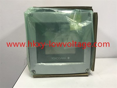
Yokogawa FLXA21 HART Conductivity Analyzer with Pipe and Wall Mounting Hardware
The Yokogawa FLXA21-D-P-D-AB-C1-NN-A-N-LA-N-NN/U is a general-purpose contacting-conductivity analyzer supplied in the plastic-housing, anti-glare-display configuration with pipe and wall mounting hardware. Its A output code identifies a two-wire 4–20 mA signal with HART communication. The model is intended for a single compatible conductivity sensor because the second input position is specified as NN.
This combination is practical for retrofit projects that retain an existing analog control-system input while adding digital access for setup and diagnostics. It can serve water preparation, cooling towers, rinse systems, chemical make-up, condensate monitoring, wastewater treatment, and packaged equipment. Because the model string in the workbook compresses the A and N positions as “AN,” the purchase order should preserve the manufacturer’s exact separator format.
Retrofit questions before purchase
Record the existing analyzer model, sensor model, cell constant, temperature element, cable type, output range, supply voltage, receiving resistance, and mounting method. Check the available pipe diameter or wall surface for the /U bracket. If the old installation uses conduit, confirm gland and entry requirements because this requested code does not list a separate conduit-adapter option.
Measure the loop voltage at the instrument under operating load. The supply must cover the analyzer, receiver, cable loss, and any isolator or surge protector. HART communication needs a suitable network impedance and compatible modem or input card. A loop can carry a correct analog value yet provide unreliable digital communication if its impedance, noise, or grounding is unsuitable.
| Replacement check | Requested detail |
|---|---|
| Complete model | FLXA21-D-P-D-AB-C1-NN-A-N-LA-N-NN/U |
| Input module | C1 contacting conductivity; single-channel arrangement |
| Control signal | 4–20 mA with HART communication |
| Site classification | AB general-purpose configuration |
| Mounting accessory | /U pipe and wall mounting hardware |
| Language | LA multilingual display set |
Getting a trustworthy conductivity value
Select the sensor around the real process envelope, not only the normal reading. The cell constant, electrode material, geometry, pressure rating, temperature rating, and process connection must cover startup, cleaning, and upset conditions. Decide whether two-electrode or four-electrode construction is appropriate. Verify that the sensor cable and extension arrangement are approved for the intended measurement range.
Temperature compensation requires equal attention. Set the analyzer for the actual temperature element and choose a compensation model that represents the liquid. In a rinse-water system, trending uncompensated and compensated values can help distinguish temperature variation from contamination. In concentration service, obtain process-specific data before treating conductivity as a direct concentration measurement.
Mounting and wiring practice
Use the /U hardware to support the enclosure without twisting the housing or cable entries. Position the display for routine reading and leave clearance for opening and service. Avoid direct heat, severe vibration, and locations where washdown water can collect around poorly sealed entries. Maintain separation between low-level sensor wiring and power cables.
Connect shielding and grounding according to the analyzer and sensor manuals. Enter the sensor cell constant exactly, then configure measurement units, output scaling, damping, burnout direction, tag, and diagnostic limits. If the analyzer replaces another model, do not assume the same terminal numbers or default failure current.
Acceptance test and maintenance record
At commissioning, compare the analyzer with a suitable conductivity standard or controlled reference. Test the analog loop at the control system, establish HART communication, and verify that the tag and range are correct. Record the as-left parameters, sensor serial number, cell constant, calibration result, and installation date. These records make later drift analysis more reliable.
During service, clean the sensor using a method compatible with its materials and the deposit. Inspect for corrosion, cracked insulation, trapped air, and unstable temperature. Calibration should not be used to hide an installation problem. The page reuses the existing FLXA21 image because the workbook specifies the same source photograph; the exact requested suffix must be confirmed from the nameplate and order acknowledgment.
