

Yokogawa FLXA21 Intrinsically Safe Conductivity Analyzer for Hazardous Process Areas
The Yokogawa FLXA21-D-P-D-CB-C1-NN-A-N-LA-N-NN/U/SCT is a configured two-wire liquid analyzer for contacting-conductivity service in projects that require an intrinsically safe instrument design. The C1 code identifies a contacting-conductivity input, while the CB approval code is associated with an intrinsically safe ATEX and IECEx configuration in Yokogawa ordering literature. The analyzer is intended to work with a compatible conductivity sensor, loop supply, control-system input, and approved intrinsic-safety interface.
This configuration is especially relevant where water quality or solution concentration must be measured close to process equipment located in a classified area. Typical duties include chemical transfer, solvent recovery support, utility-water monitoring, neutralization skids, cleaning systems, and conductivity-based interface detection. The complete measuring loop must be engineered as a system; selecting an approved analyzer does not by itself make the sensor, barrier, cabling, glands, and installation compliant.
Why the full configuration matters
FLXA21 is a modular analyzer family, so similar front panels can conceal important differences. The listed P housing code denotes the plastic enclosure, D denotes the anti-glare display, C1 selects contacting conductivity, and A indicates a 4–20 mA output with HART communication. The /U option is used for pipe and wall mounting hardware, and /SCT should be verified against the current order document as the requested tag-plate treatment. Buyers should match the entire code rather than accepting an analyzer identified only as “FLXA21.”
Yokogawa publishes support for two- and four-electrode conductivity measurement, with family cell constants from 0.005 to 50 cm⁻¹. The useful range depends on the sensor, cell constant, temperature element, process composition, and installation. Conductivity may be displayed from very low microsiemens values through high-conductivity process ranges, but the application should be designed around the actual sensor rather than the analyzer’s broad theoretical capability.
| Verification point | Requested product information |
|---|---|
| Model | FLXA21-D-P-D-CB-C1-NN-A-N-LA-N-NN/U/SCT |
| Measurement channel | C1 contacting conductivity; second input not fitted |
| Area configuration | CB intrinsically safe ATEX/IECEx configuration; certificate and entity parameters must be checked |
| Output | Two-wire 4–20 mA with HART for the A output code |
| Mounting | /U pipe and wall mounting hardware |
| Enclosure family | Plastic housing, IP66/NEMA 4X-class protection subject to the exact approval and installation |
Engineering the conductivity loop
Begin with the expected minimum and maximum conductivity, normal and upset temperatures, pressure, chemical compatibility, flow velocity, and fouling tendency. Low-conductivity water normally requires a low cell constant and careful sample handling, while stronger chemical solutions may require a higher cell constant and electrode materials selected for corrosion resistance. Confirm whether a two-electrode or four-electrode sensor is more appropriate and whether the required cable length is supported.
Temperature compensation must also be defined. A stable concentration can produce a changing conductivity reading as temperature moves, so the configured temperature sensor, reference temperature, and compensation curve must match the process. For high-purity water, confirm whether pure-water compensation is required. For blended chemicals, determine whether a standard NaCl relationship is suitable or whether a process-specific matrix is necessary.
Hazardous-area installation review
For an intrinsically safe loop, compare the analyzer and sensor control drawings with the isolator or barrier certificate. Verify voltage, current, power, capacitance, inductance, cable parameters, grounding method, segregation, glands, and enclosure entries. The loop supply must provide sufficient voltage after accounting for the receiving resistor, barrier drop, cable loss, and analyzer requirement. HART communication also requires a compatible load and interface.
Mount the analyzer where the display is readable and the enclosure can be serviced without stressing the cable entries. Seal unused entries, keep sensor wiring separate from power and variable-frequency-drive cables, and document the final terminal assignments. The /U hardware should be checked for the intended pipe diameter or wall arrangement before shipment.
Commissioning and maintenance
Commissioning should confirm the sensor cell constant, temperature element, measurement units, range, output scaling, damping, alarms, burnout direction, and HART tag. Validate the loop at several simulated output points and compare the installed sensor with a suitable reference or conductivity standard. Record the configuration so a replacement can be restored without guessing.
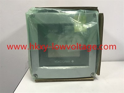
Routine checks should include electrode cleanliness, insulation condition, cable seals, temperature response, and comparison with laboratory data. A gradual shift can indicate coating or aging, while an abrupt change may be caused by air bubbles, wiring damage, a real process upset, or an incorrect compensation setting. The photograph is a family reference because the nameplate is not fully visible; final acceptance must be based on the complete requested model and current Yokogawa documentation.
