


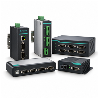
Moxa — Eight-channel serial topology and surge/isolation review for CP-118E-A-I
| Device role | eight-port PCI Express serial board |
|---|---|
| Product model | CP-118E-A-I |
| Key configuration | Confirm eight-port capacity and supported line modes |
| Interface check | Check cable/connector accessories for the order code |
| Installation | Verify host slot and operating-system driver |
| Acceptance | Test each port with its intended device |
The CP-118E-A-I is considered here as a eight-port PCI Express serial board. Eight-port pci express serial-board model in moxa's cp-118e-a-i family; verify the exact cable, supported serial modes, electrical protection and current driver matrix for the installed host.. Before selecting the CP-118E-A-I, map the complete path from field signals and network boundaries to the host system, supply source and operating location.
Design brief
The information needed to quote a CP-118E-A-I accurately includes the full model code, quantity, installation country, host platform, network or fieldbus details, environmental conditions and any required accessories. Include a wiring sketch or port schedule where useful. This lets a reviewer confirm whether the selected CP-118E-A-I and its variant align with the actual installation.
Connection and environment
For a CP-118E-A-I enquiry, begin with the device that must connect, the protocol on each side and the owner of the communication session. Record the required direction of data flow and identify whether the CP-118E-A-I is expected to initiate requests, respond to a controller or simply pass traffic. These details determine a workable configuration more reliably than a model-family name alone.
Integration workflow
The physical design around CP-118E-A-I should be checked before commissioning. Confirm connector type, cable medium, termination, grounding, power availability and any environmental suffix. A nominal protocol match does not guarantee the cable or electrical interface is compatible; document each endpoint and its pin or port assignment before energizing the CP-118E-A-I.
Fault isolation
During integration, configure the CP-118E-A-I against an approved network plan rather than assigning addresses informally at the cabinet. Capture VLAN or subnet boundaries where applicable, device names, serial settings, firmware baseline and the expected diagnostics. A commissioning record makes later service work on the CP-118E-A-I much faster and helps separate wiring faults from application mapping errors.
Procurement checklist
A staged acceptance test for CP-118E-A-I should prove the local link first, then the protocol exchange and finally the full application value. Compare a known input or register with the value at the consuming system, check alarm behavior, and record recovery after a controlled link interruption where site procedures permit. Save the result with the exact CP-118E-A-I identifier.
Design brief
For replacement planning, retain the CP-118E-A-I part code, suffix, connector details, firmware and accessory list alongside the as-built drawing. If the site has an established configuration, compare it with the proposed CP-118E-A-I replacement before changing the device; small suffix differences can affect temperature, optical interface, power input or included cable options.
Connection and environment
The CP-118E-A-I selection should also account for maintenance access. Identify who owns firmware updates, where configuration backups are stored and how alarms reach the operations team. If several CP-118E-A-I devices are deployed, keep one inventory row per physical unit with its location, address, attached equipment and validated configuration instead of relying on an unstructured label list.
Integration workflow
Before issuing a purchase order for CP-118E-A-I, ask the site team to verify the complete nameplate, target application, environmental range and required accessories. Confirm that the quantity covers the installed topology and any approved spare policy. This final review reduces avoidable substitutions and keeps the delivered CP-118E-A-I aligned with the approved bill of materials.
Fault isolation
Keep the CP-118E-A-I design within documented operating limits and the project's cybersecurity and safety procedures. Apply only approved network services, protect management access, use the required grounding and isolation practices, and validate the finished installation against current manufacturer documentation. The CP-118E-A-I should be treated as one element in a system-level design, not as a substitute for the system review.
Procurement checklist
When the CP-118E-A-I is part of a migration, record the old interface and behavior before disconnection. Note timing, addressing, scaling and fail-state behavior, then compare these with the new CP-118E-A-I configuration under a controlled test. Preserve a rollback path until the application owner accepts the observed result and the maintenance team has the final record.
Procurement checklist
- CP-118E-A-I w/o cable
