


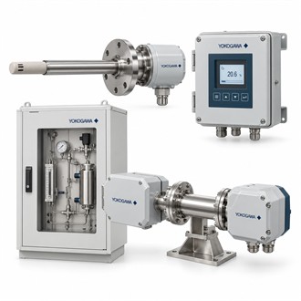
Detector and sample-system review for Yokogawa GD402G-A-E-E/PA/M1
Yokogawa GD402G-A-E-E/PA/M1 is a GD402 gas-density converter configuration. This selection overview brings the product role, installation interfaces and purchasing details together. For an existing installation, identify GD402G-A-E-E/PA/M1 from the complete equipment nameplate and compare the ordered build with the current drawings before arranging supply.
Configuration at a glance
| Selection point | Specification / confirmation |
|---|---|
| Representative model | GD402G-A-E-E/PA/M1 |
| Equipment role | Gas-density analyzer converter |
| Measuring assembly | Used with a compatible gas-density detector |
| Application inputs | Gas composition and sample conditions |
| Confirm | Detector, converter options, outputs and mounting |
The converter requires the correct detector
GD402G-A-E-E/PA/M1 is the converter portion of a gas-density measuring arrangement. Selection must identify the associated detector and the intended gas application, rather than treating the converter as a complete independent measuring sensor. For GD402G-A-E-E/PA/M1, state the density or related process variable required and verify the supported combination of detector, converter and configured outputs.
- Associated detector model and condition
- Gas composition and sample pressure/temperature
- Configured variable, range and output
- Sample conditioning and calibration arrangement
Describe the sample conditions accurately
The process review for GD402G-A-E-E/PA/M1 should include the gas composition, pressure, temperature, sample flow and the presence of moisture or contaminants. Those details determine the suitable sampling arrangement and operating limits of the measuring system. When ordering GD402G-A-E-E/PA/M1, include any existing sample-conditioning equipment and the equipment tag so the proposed supply can be checked against the installed analyzer train.
Configuration and calibration handover
Before returning GD402G-A-E-E/PA/M1 to service, confirm detector compatibility, selected engineering units, configured ranges and output scaling. Use the applicable verification or calibration procedure for the assembled system. Record the test conditions and reference information with GD402G-A-E-E/PA/M1, including any alarm settings, so a later change in the sample system can be assessed without losing the baseline measurement setup.
Analyzer-system information for supply review
Describe the measured gas or process duty, sample conditions, associated detector and the intended control-system interface. Include the existing converter and detector nameplates, cable or terminal schedule and calibration arrangement. Clarify the supply boundary between instrument hardware, sample conditioning and separately supplied accessories. The final review should compare the complete measuring system with the plant requirements and retain the agreed configuration for commissioning. Preserve the exact GD402G-A-E-E/PA/M1 designation on the enquiry and confirm the offered GD402G-A-E-E/PA/M1 configuration before release.
Comparing the offered configuration
When comparing offers for GD402G-A-E-E/PA/M1, review the complete configuration and package scope together with the technical requirement. Clarify the condition of the equipment, the supplied accessories and the available documentation. The purchase record for GD402G-A-E-E/PA/M1 should retain the agreed code and any application-specific requirements, allowing receiving inspection and the installation team to verify the same information without reconstructing the original enquiry.
