


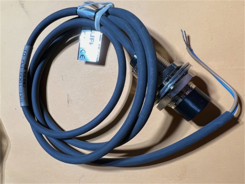
Balluff NB-RXE-1805P-PU03 Remote Sensor Output Unit
The Balluff NB-RXE-1805P-PU03 is listed as a remote-sensor output component for contactless signal transmission across a small air gap. This type of system is useful where conventional connectors or cable runs would be exposed to repeated motion, contamination, mechanical wear, or difficult access. Typical applications include rotating fixtures, changeable tooling, transfer systems, robot end effectors, assembly machines, and automated material handling.
Published information for the related RXE-1805P family describes a PNP output unit working with a matching M18 transmitter in a one-signal remote sensor system. Family data includes 24 VDC operation, one output signal, load current up to 100 mA, switching frequency around 25 Hz, output indication by LED, and short-range contactless transmission. Exact cable length, connector, suffix, rated distance, enclosure rating, and compatible transmitter must be confirmed for NB-RXE-1805P-PU03.
Why Use a Remote Sensor System
- Transfers a sensor switching signal without exposed electrical contacts at the moving interface.
- Reduces connector wear during frequent fixture or tooling changes.
- Supports PNP control circuits commonly used in industrial automation.
- Compact cylindrical format for installation near machine tooling and positioning equipment.
- LED indication assists commissioning and maintenance checks.
- Helps simplify wiring at locations where a direct cable connection is inconvenient.
Selection and Installation Notes
A remote sensor output unit must be paired with the correct transmitter or detector component. Before ordering, verify the matching series, PNP or NPN output logic, supply voltage, cable length, connector style, load current, switching frequency, mounting distance, permitted offset, surrounding-metal clearance, operating temperature, and protection rating. The PLC input and machine grounding arrangement should be checked as part of commissioning.
Mechanical alignment affects reliable energy and signal transfer. Install both faces squarely, maintain the specified gap, and avoid metal or adjacent devices closer than the manufacturer’s minimum spacing. Flexible cable sections should be supported and protected from repeated bending, sharp edges, coolant, and impact. Test the complete machine cycle after installation, including the largest expected offset and vibration condition.
Automation Use Cases and Control Integration
Contactless sensor transmission is particularly useful on fixtures that are exchanged many times per shift. Instead of asking an operator to connect a plug manually, a correctly designed remote system can establish the signal path when the tooling reaches its working position. This can reduce connector damage, incorrect reconnection, and maintenance time in welding cells, pallet-transfer lines, indexing tables, packaging machinery, and robotic handling systems.
The control program should distinguish between the machine sensor state and the health of the contactless link. Where possible, commissioning should verify power indication, output indication, target status, and the PLC input separately. The designer should consider what the machine must do if the receiver is misaligned, the transmitter is absent, the cable is damaged, or the output remains inactive. A defined safe response and clear diagnostic message make troubleshooting faster and help avoid confusing a transmission problem with a failed process sensor.
Replacement and Acceptance Testing
When replacing an existing device, record the installed orientation, face-to-face distance, bracket dimensions, connector keying, cable routing, and PLC terminal assignment before removal. A family-compatible part may still differ in cable length, connection method, sensing direction, or switching logic. The new unit should not be accepted only because its housing looks similar; the complete order code and mating component must agree with the machine documentation.
After installation, test the system at minimum and maximum operating gaps, through the full motion cycle, and under normal vibration. Confirm switching at the expected machine speed and check that nearby metal, motors, weld current, or variable-frequency drives do not produce intermittent behavior. Record the final gap and alignment so future maintenance technicians have a reference. For critical tooling, keeping a verified transmitter-and-receiver pair as a spare can simplify recovery and reduce production downtime.
Photo and Part-Number Verification
The supplied photograph shows a cylindrical unit labeled RXT-1805-PU-01. That label does not match the requested NB-RXE-1805P-PU03 output-unit code. The photo is therefore a related remote-system reference only. Buyers must verify the exact component role, label, PNP output, cable suffix, mating part, and legacy Balluff or associated manufacturer documentation before accepting a replacement.
For a quotation, send clear photos of the existing nameplate and connector, the complete model code, required quantity, mating transmitter, PLC input type, operating gap, cable length, and delivery destination. This prevents a transmitter, detector, or output unit from being supplied in place of the required component.
