


Pepperl+Fuchs HiD2082 Dual-Channel Temperature Converter
The Pepperl+Fuchs HiD2082 is a dual-channel temperature converter and isolated barrier for process measurement systems using thermocouples, resistance temperature detectors, millivolt sources, or potentiometers. It converts field temperature signals into standardized analog outputs while providing galvanic isolation and diagnostics between the field circuits and the control system.
Manufacturer information identifies two channels, 24 VDC bus-powered operation through a compatible termination board, configurable thermocouple, RTD, or potentiometer inputs, and linearized 4–20 mA sink/source or 1–5 V outputs. It can also be configured as a signal splitter with one input and two outputs. Sensor breakage and line-fault monitoring help maintenance teams recognize wiring or sensor problems.
Key Functions for Process Plants
- Two independent temperature-conversion channels in one module.
- Input support for common thermocouple, RTD, millivolt, and potentiometer sensors.
- Linearized current or voltage outputs for PLC and DCS analog input cards.
- PACTware-based configuration for sensor type, range, diagnostics, and output behavior.
- Sensor-breakage and line-fault monitoring for maintenance visibility.
- Functional-safety capability up to SIL 2 when applied according to the safety documentation.
System Compatibility Checks
The HiD2082 is designed for use with an appropriate HiD termination-board system. Confirm the board type, slot assignment, bus power, output wiring, collective error messaging, configuration interface, and control-system input arrangement before ordering. Sensor type, number of wires, measuring range, cold-junction method, lead resistance, burnout direction, and output scaling must match the application.
For safety-related service, review the applicable safety manual, proof-test interval, diagnostic coverage, failure response, and lifecycle documentation. Hazardous-area parameters, channel separation, grounding, shielding, and maximum permitted voltages must be evaluated by qualified personnel. SIL capability of the module does not by itself make the complete loop compliant.
Temperature Loop Engineering
Each channel should be engineered from the sensor through to the control-system input. For thermocouples, confirm type, polarity, compensation cable, cold-junction arrangement, grounded or ungrounded junction, and required burnout direction. For RTDs, verify the element standard, two-, three-, or four-wire connection, excitation and lead-resistance compensation. Potentiometer inputs require the correct total resistance and wiring arrangement. Incorrect sensor selection or terminal assignment can produce a plausible but inaccurate temperature value.
Output scaling should match the DCS or PLC database exactly. Record the lower and upper range values, engineering units, output mode, damping, alarm current, and line-fault behavior. If the device is configured as a splitter, both receiving loops must be checked for load and isolation requirements. The maintenance strategy should state how technicians will distinguish an open sensor, shorted wiring, out-of-range process condition, and module fault.
Commissioning and Maintenance Practice
Commissioning should include inspection of the termination board, module keying, channel wiring, shield grounding, collective-error connection, and power supply. Apply representative simulated inputs at multiple points across each configured range and compare both analog outputs with the expected values. Confirm cold-junction compensation where applicable, verify fault indication by safely opening the sensor circuit, and save the final configuration file with the loop documentation.
For routine maintenance, inspect terminal condition, cabinet temperature, grounding, and diagnostic indications before replacing the converter. A problem attributed to the module may originate in the field sensor, extension cable, termination board, power bus, or control-system channel. Keeping a known-good configured spare and a controlled parameter backup can shorten troubleshooting time. Any replacement used in a safety instrumented function must follow the site's management-of-change, proof-test, and functional-safety procedures.
Photo and Model Verification
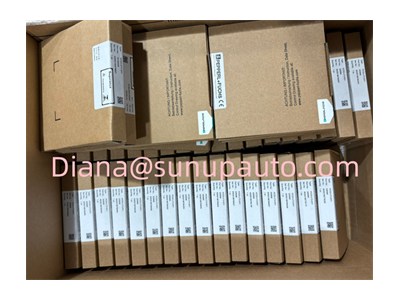
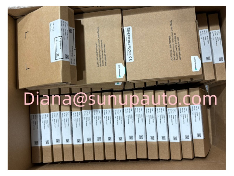
The supplied photograph shows a mixed inventory of Pepperl+Fuchs cartons. Several visible labels appear to be KCD-series products rather than HiD2082. The image is included only as a customer-supplied brand reference and must not be used to identify the requested converter. Verify the HiD2082 model, channel count, nameplate, terminal-board compatibility, approvals, firmware, and certificates before dispatch.
For an accurate quotation, provide the sensor types and ranges for both channels, required output signals, termination-board model, hazardous-area classification, SIL requirement, quantity, destination, and certification needs. Replacement inquiries should include photos of the installed module and board so that electrical and mechanical compatibility can be checked.
